
Introduction to Alternating Current (AC Circuits, LCR & Power Factor)
Understand AC vs DC current, LCR circuit behavior, power factor correction, and AC‑to‑DC conversion techniques.
⚡ What Is Alternating Current (AC)?
Alternating current (AC) reverses its direction periodically. This characteristic allows AC voltage to be easily changed using transformers. Many power grids and household outlets rely on AC because it is the most efficient method for long-distance power transmission. Devices like transformers and large motors are designed to work efficiently with AC power.
🔍 Fundamental Differences Between AC and DC Current
Here’s a clear and expanded comparison of **AC (Alternating Current) and DC (Direct Current) current**, detailing their characteristics, applications, and conversion methods:
| Property | AC Current | DC Current |
|---|---|---|
| **Flow** | Reverses direction periodically (e.g., a sine wave). | Flows in one constant direction. |
| **Generation** | AC generators (**alternators**), which rotate magnetic fields to induce current. | Batteries, fuel cells, and solar cells (photovoltaic effect). |
| **Transmission** | High voltage with low current minimizes losses over long distances; easily stepped up/down via **transformers**. | Less efficient for long distances; conversion to high voltage requires complex electronic **inverters**. |
| **Primary Use** | Power distribution grid, large industrial motors, most home appliances. | All electronic devices (phones, computers), batteries, LED lighting. |
| **Voltage Change** | Easy using simple, efficient transformers. | Requires complex DC-to-DC converter circuits. |
| **Conversion** | Requires **rectifiers** (diodes) to convert to DC. | Requires **inverters** to convert to AC. |
In summary: AC is optimally suited for massive scale transmission, while DC is the standard for efficient storage and powering sensitive electronics.
🔁 AC Voltage and Current in LCR Circuits: The Role of Impedance
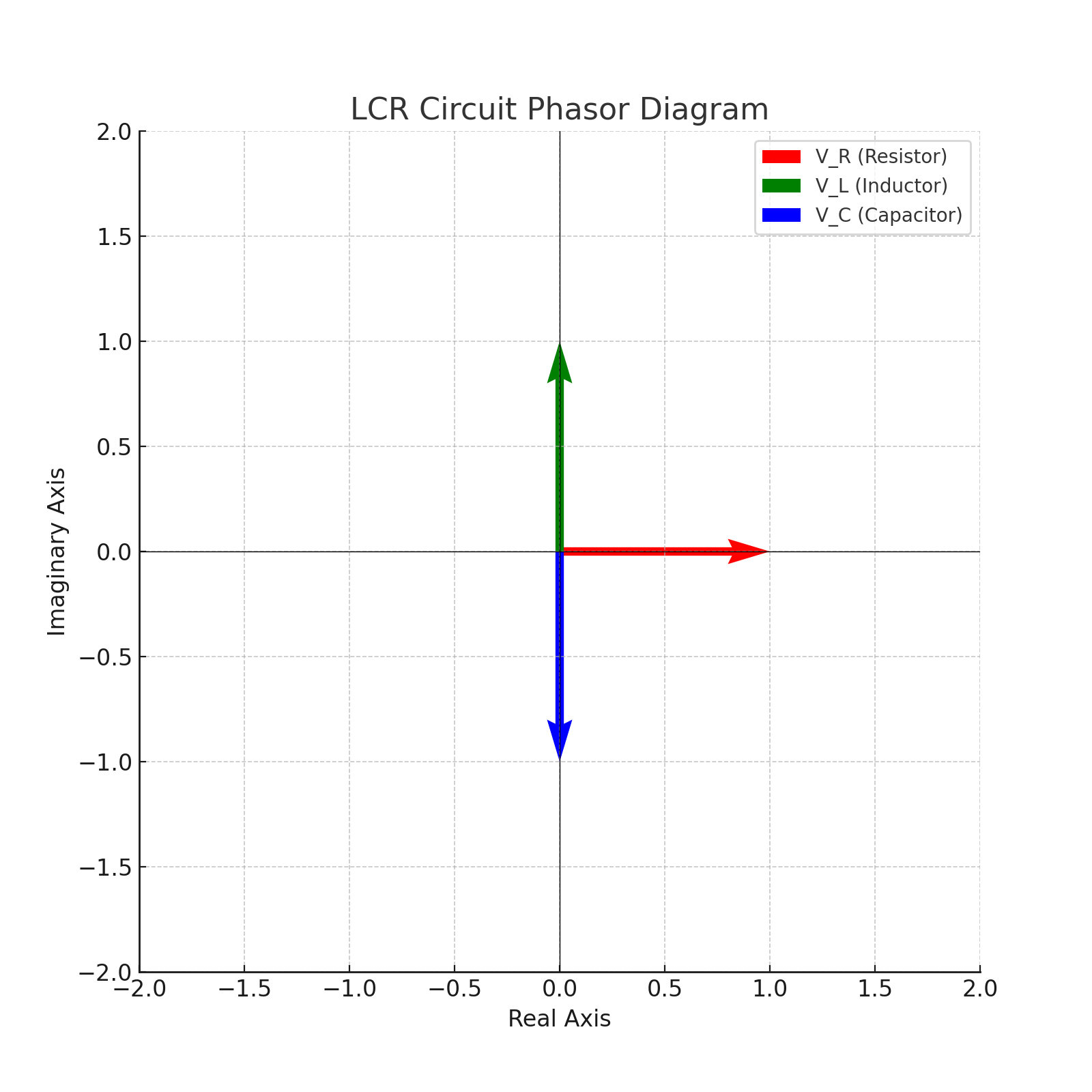
When an AC voltage is applied to a series **LCR (Inductor‑Capacitor‑Resistor) circuit**, the resulting current flow is governed by the combined opposition of the three components, known as **Impedance ($Z$)**. This circuit is crucial for understanding AC behavior, resonance, and filtering applications.
- **Capacitive Reactance ($X_C$)**: The opposition from the capacitor, which causes the current to **lead** the voltage. $$ X_C = \frac{1}{2\pi f C} $$
- **Inductive Reactance ($X_L$)**: The opposition from the inductor, which causes the current to **lag** the voltage. $$ X_L = 2\pi f L $$
- **Impedance ($Z$)**: The total effective opposition to AC flow, calculated using a vector sum. $$ Z = \sqrt{R^2 + (X_L – X_C)^2} $$
- **Phase Angle ($\phi$)**: The phase difference between the resultant voltage and current waveforms. $$ \phi = \tan^{-1}\left(\frac{X_L – X_C}{R}\right) $$
🔧 Power Factor & Power Analysis in AC Circuits
The **Power Factor (PF)** is a critical metric for efficiency in AC circuits. It is defined as the ratio of real power to apparent power ($\text{PF} = P/S$). A PF close to 1.0 (or unity) means the circuit is using the supplied power most effectively. The PF is mathematically equal to $\cos \phi$, where $\phi$ is the phase angle calculated in the LCR circuit analysis.
- **Real Power ($P$)**: The power that actually does useful work (converted to heat, light, or mechanical energy). $$ P = VI\cos \phi $$
- **Apparent Power ($S$)**: The total power delivered by the source (Volt-Amperes). $$ S = VI $$
- **Reactive Power ($Q$)**: The power exchanged between the source and the reactive components (L and C); it does no useful work. $$ Q = VI\sin \phi $$
Industrial applications often use **power factor correction** techniques (e.g., adding capacitor banks) to bring the PF closer to 1.0, reducing energy losses and utility costs.
🔄 The Process of Converting AC to DC Current
Since most electronics require DC, a multi-stage process is necessary to reliably convert the AC grid power into steady DC voltage. This process is typically housed within a power supply unit or a wall adapter:
- Rectifier Circuits: The initial stage uses diodes (often in a **bridge rectifier** configuration) to convert the alternating AC waveform into a pulsating, single-direction DC waveform.
- Capacitor Filters: Large electrolytic capacitors are used to smooth out the pulsating DC output by storing charge during the peaks and releasing it during the troughs, significantly reducing the “ripple” voltage.
- **Voltage Regulators:** Finally, integrated circuit regulators (ICs) or Zener diodes are used to maintain the output at a precise, steady DC voltage level, compensating for minor changes in the load or input AC voltage.
🛠️ AC‑to‑DC Current Converter Tool (Simulation)
This simple tool simulates the estimated DC peak voltage output from an AC input voltage for a basic full-wave rectifier and filter circuit, accounting for standard diode drops ($\approx 2 \times 0.7 \text{ V}$ for silicon diodes).
Estimated DC Peak Output (Unregulated): — V
🧠 Real‑World Applications and Significance
The duality of AC and DC is essential to modern society:
- **Household Distribution:** All main wiring and sockets in homes use **AC distribution** because of the ease of voltage transformation for safety and efficiency.
- **Electronics:** Every computing device, from smartphones to servers, relies on an internal or external circuit to perform **rectification from AC to DC current**.
- **Industry:** Large **industrial motors** (especially induction motors) and power-handling **transformers** are inherently designed to run on AC.
- **Efficiency:** Large consumers of power, such as factories, actively implement **power factor correction** systems to save energy and avoid penalties from utility companies for inefficient power use.
Power Factor Calculator
Enter Real and Apparent Power to calculate power factor (PF = P/S).
Power Factor (cos φ): –
LCR Resonant Frequency Calculator
Enter inductance (L) and capacitance (C) to compute the resonance frequency ($f_r$).
$$ f_r = \frac{1}{2\pi \sqrt{LC}} $$
Resonant Frequency ($f_r$): – Hz
📚 Common AC vs DC Current FAQs
1. What is the main characteristic difference between AC and DC current?
The primary difference is the direction of flow: **AC current** periodically reverses its direction, making it suitable for transformers and long-distance transmission, while **DC current** flows in a single, constant direction, which is necessary for electronics and battery storage.
2. Why is AC (Alternating Current) used for large-scale power transmission?
AC is used because its voltage can be easily and efficiently increased (stepped up) using **transformers** for transmission. Transmitting at high voltage significantly **reduces current**, which in turn drastically **lowers power losses** due to resistance ($P_{\text{loss}} = I^2R$) across long power lines.
3. Can a device use both AC and DC current?
Virtually all modern electronic devices that plug into a wall outlet are considered “AC-powered,” but they internally contain a **power supply unit** to convert the incoming AC to the necessary DC for their internal circuitry. Therefore, they consume AC but operate on DC.
4. What exactly does power factor measure?
The **power factor ($\cos \phi$)** measures the efficiency of an AC circuit. It is the ratio of the power used to perform useful work (Real Power) to the total power supplied (Apparent Power). A PF of 1.0 (or unity) represents perfect efficiency, where all the supplied power is used for work.
5. How do I convert AC to DC current?
The conversion is done using a circuit that includes a **rectifier** (typically diodes) to turn AC into pulsating DC, followed by a **capacitor filter** to smooth the pulsations, and finally a **voltage regulator** to output a clean, stable DC voltage suitable for electronics.